DEPARTMENT OF MECHANICAL ENGINEERING
DESIGN RESEARCH CENTRE

| DEPARTMENT OF MECHANICAL ENGINEERING DESIGN RESEARCH CENTRE |
|
|
| Introduction Partner Links Project Objectives Main Activities Project Publications Further Information |
Guidance
on the Design of Ships for Enhanced Escape and Operation Project "EGO" (Evacuation Guidance and Operations) EPSRC funded project, 2005-2007 |
|||||||||||||||||||||||||||||||||||||||||||
Return to top |
Introduction Traditionally, when designing a ship the driving issues are seen to be powering, stability, strength and seakeeping. When the broad form of the layout has been finalised, human factors issues related to crew numbers, ship operations and evolutions, such as evacuation, are either ignored, considered as an after thought or incorporated through a set of prescriptive rules. This can result in significant operational inefficiencies and potentially hazardous environments onboard. The overall objective of this multidisciplinary research project is to show the advantages of integrating the cutting edge technologies of Ship Configurational Design (i.e. SURFCON developed by the Marine Research Group of UCL) and Escape Simulation (i.e. maritimeEXODUS developed by the FSEG of the University of Greenwich). This will enhance the guidance for all parties in the design, regulation, construction and operation of ships with regard to the main aspects of personnel movement onboard. To achieve this, the project draws on the well-established expertise of the Design Research Centre, Marine Research Group of UCL in the area of ship architecture design and of the FSEG of the University of Greenwich in the area of fire and evacuation modelling. While this project addresses the design of naval vessels, the principle behind the proposed methodology and the tool set produced have direct application to the design of commercial and passenger vessels. |
|||||||||||||||||||||||||||||||||||||||||||
Return to top |
Partner
Links Design Research Centre Department of Mechanical Engineering UCL Fire Safety Engineering Group School of Computing & Mathematical Sciences the University of Greenwich Directorate of Sea Systems Defence Equipment and Support UK Ministry of Defence |
>> UCL DRC Link << >> UoG FSEG Link << >> MoD DSS DE&S Link << |
||||||||||||||||||||||||||||||||||||||||||
Return to top |
Project
Objectives This project had five main objectives: 1. To explore the impact on naval ship configurational design of issues associated with crew manning numbers, function and movement. 2. To identify key performance measures for successful crew performance in normal and extreme conditions. 3. To extend the ship evacuation software maritimeEXODUS to include additional non-emergency personnel movement simulation capabilities. 4. To extend the ship design software so that it can provide a modeling environment that interactively accepts maritimeEXODUS simulation output for a range of crew evolutions. 5. To demonstrate a methodology for ship design that integrates ship configuration design with modeling of a range of crewing simulation issues through PARAMARINE-SURFCON. |
|||||||||||||||||||||||||||||||||||||||||||
Return to top |
Main
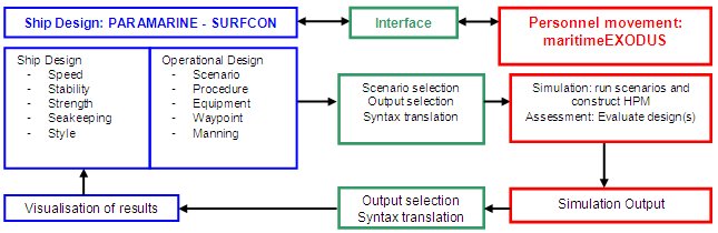
Activities Figure 1 illustrates the overall relationship between the expertise domains and software tools on which each research partner led. This shows, in flowchart form, the design and analysis activities that were carried out in each of the tools. The interface tools developed in this project were separate from the PARAMARINE-SURFCON and maritimeEXODUS software and permitted the required information to be transferred between them.
In addition to developing models of the baseline vessel (Type 22 Batch III frigate) and varaints, the UCL DRC was involved in several other main activities in this project. 1. Representing the Design in PARAMARINE-SURFCON
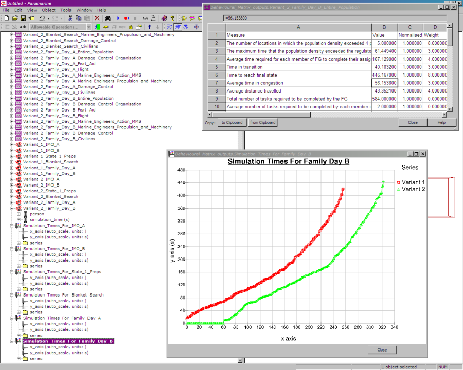
In addition to these representations of the physical ship configuration and connectivity, the UCL team also developed a method for describing the Watch and Station Bill (W&SB). This is a table stating the location and activities of each member of the crew in each of the defined operating conditions and evolutions (e.g. State 1, Replenishment at Sea). In the PARAMARINE-SURFCON model this location information is linked to the configurational model of the vessel, thus allowing the layout of the design to be altered without manual editing and updating of the W&SB. 2. Transferring the Design Definition As noted above, in order to perform simulations of personnel movement in the ship designs, martimeEXODUS requires several different types of information regarding the ship design and the scenarios to be assessed. Most of these pertain to the ship design under examination, and so were included in the Design Building Block model. Two existing PARAMARINE file formats were utilised to output the design information, and a UCL developed tool extracted the relevant information from these and input files for martimeEXODUS and the UoG developed Scenario Generator. The types of information transferred can broadly be categorised as Geometric, Connectivity and Procedural. Geometric Data This primarily concerns the division of the ship into watertight and non-watertight spaces, as shown in Figure 3. In maritimeEXODUS, each of the resulting areas, if accessible to personnel, would be described as a grid of nodes. The transfer of this data utilised two approaches. A DXF file containing a line drawing of each deck was generated in PARAMARINE-SURFCON and transferred without any editing. In addition to this, a KCL file was generated describing the Design Building Block hierarchy used to represent the ship design. This is a maro file, in that it contains a series of instructions that can be used by PARAMARINE to reconstruct the design, rather than an absolute numerical statement of the current configuration. Thus a tool was written that is able to parse this complex macro file and resolve the locations of selected objects such as the doors and ladders. As any space that is accessible to the crew must have at least one door or hatch accessing it, it was possible to use these to explicity define the location and name of each of the regions of nodes representing each of the spaces in the ship, thus completing the geometric definition of the design. Connectivity Data This refers to the doors, hatches, ladders and stairs added to the design. The KCL resolution tool outlined above produced input files for maritimeEXODUS containing data on the location, orientation and type of each of these connectivity items. The definition of these items in PARAMARINE-SURFCON utilised the existing functionality, and additional entities can be created as the field of personnel movement simulation is further explored. Procedural Data This refers primarily to the Watch and Station Bill, which, by stating the location and activity of each crew member in each readiness state and ship evolution, contatins all procedural data required. By including this information in the PARAMARINE-SURFCON model it is possible to link W&SB locations (such as the bridge) directly to their Design Building Block counterparts. The significance of this is that the spatial configuration of the design can readily be changed without the need to re-define the W&SB. Alternatively a different operating philosophy can be investigated by chaging the links to relocate individuals in the vessel. In addition to the start and end positions of each individual in the crew, also defined are significant waypoints through which they must pass in some evolutions. One example of this is the lockers used to store fire-fighting gear, which must be aquired by damage control teams before they can report ready. Again, this made use of existing PARAMARINE-SURFCON functionality and the KCL file. The significance of these developments is that, if the described standards of definition of the geometry, connectivity and procedural data are adhered to, then the translation tools can be used to define any vessel in martimeEXODUS, ready for personnel simulation. The flexibility of PARAMARINE-SURFCON effectively extends this to include any populated environment that can be modelled. 3. Viewing and Investigating Simulation Results As the naval architectural part of the project team, the UCL DRC had a particular interest in the development of tools and procedures for viewing and investigating the results of the simulation. This would help place the numerical data contained in the Behavioural Matrix (BMX) in context. Initially, the possibility of modifications to the PARAMARINE-SURFCON software were investigated, but subsequently existing functionality and tools were used to provide the developmental capability. Three main types of data were identified, with different methods used to display and investigate them. Tabular Data Certain data produced by the Human Performance Metric (HPM) is best represented in tabular form, and the existing spreadsheet functionality in PARAMARINE was used, via the KCL file format. Graph Data Line graphs were used to display variations in numerical values. Figure 4 shows the PARAMARINE-SURFCON implementations of tables and line graphs. This use of existing functionality means that additional tables and graphs can easily be added to further investigate the simulation results.
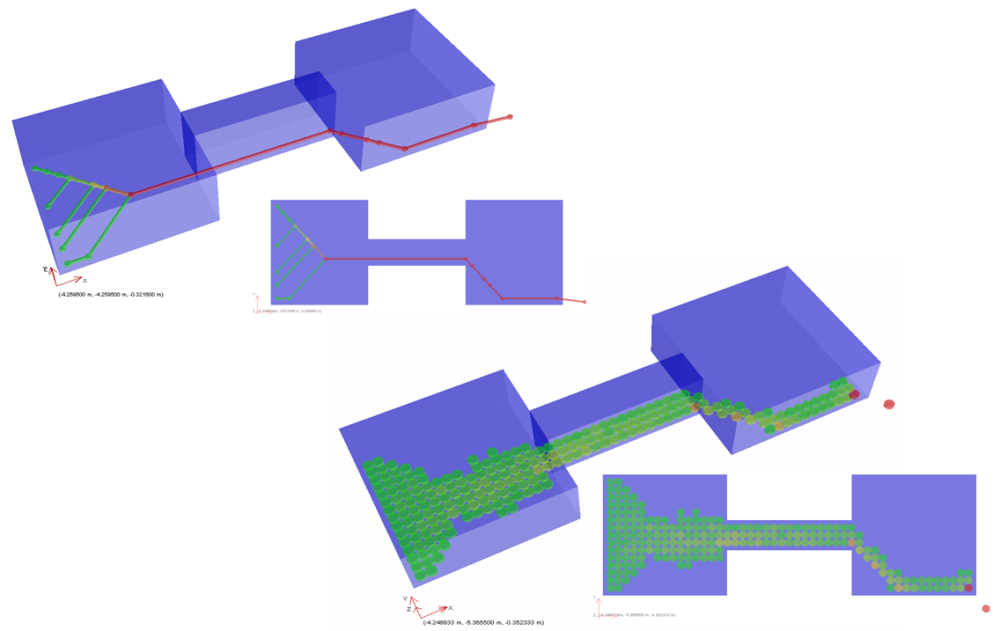
Graphical Data In order to fully utilise the simulation results in the early stages of the ship design process, they must be placed in the context of the ship design. This can be accomplished through the use of interactive computer graphics, as in the Design Building Block approach itself. In the early stages of the research project, UCL investigated the possibilities for using existing PARAMARINE-SURFCON functionality to provide such interactive representations, as shown in Figure 5.
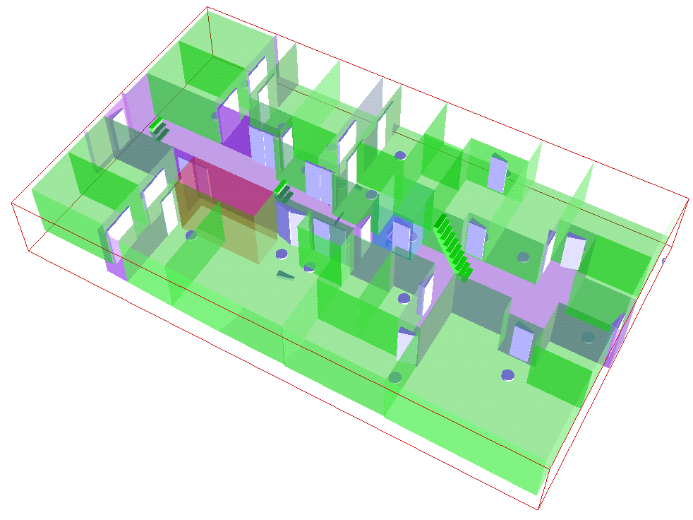
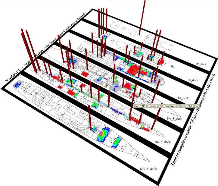
Allthough this work showed that interactive visualisations were possible in PARAMARINE-SURFCON, the resulting file sizes were unweildy for use in the fluid early stages of ship design. An alternative approach of overlaying 2D images and animations over the 3D model was proposed. Subsequent discussions with GRC (the vendor of PARAMARINE-SURFCON) indicated that the time required to make the necessary modifications for this functionality was beyond the scope of the project and so this option was not pursued within PARAMARINE. However, it was possible for UCL to develop a visualisation tool based on the Virtual Reality Modeling Language (VRML). This makes use of a third-party viewer operating within a web browser, and can provide an interactive display with 3D shapes, animated and static texture maps. The tool developed is shown in Figure 6. The footfall density map resulting from a maritimeEXODUS simulation is shown, with vertical bars providing a visual indicator of how long the watertight doors were open.
The flexible nature of this tool means that it can be adapted to display different information of interest. It also provides a clear demonstration of the functionality to be included in any future developments of the ship design software. 4. Modelling the Designs The procedure and software tools were demonstrated by application to the Type 22 Batch III Frigate design. This class is currently in service with the Royal Navy and MoD provided numerical and geometric information. In addition to producing a higher than normal resolution PARAMARINE-SURFCON model of the design as built, several variant models were produced for assessment. Importantly, each of these models represented a balanced design, containing numerical data such as weight and area requirements. The designs were assessed for performance in technical areas such as stability (intact and damaged) and powering. Thus these design models represented those that would be used in a ship design process. A significant difference, however, was that the Baseline models were at a much higher level of configurational definition than those that would be used in early stage design. Table 1 compares the level of detail in the Type 22 Batch III baseline design and in two past UCL DRC designs.
Table 1: Comparison of detail in
PARAMARINE-SURFCON design models
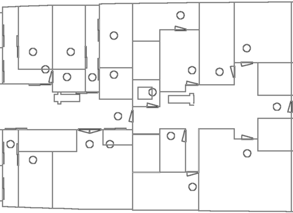
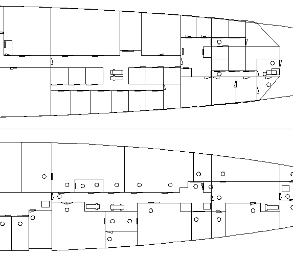
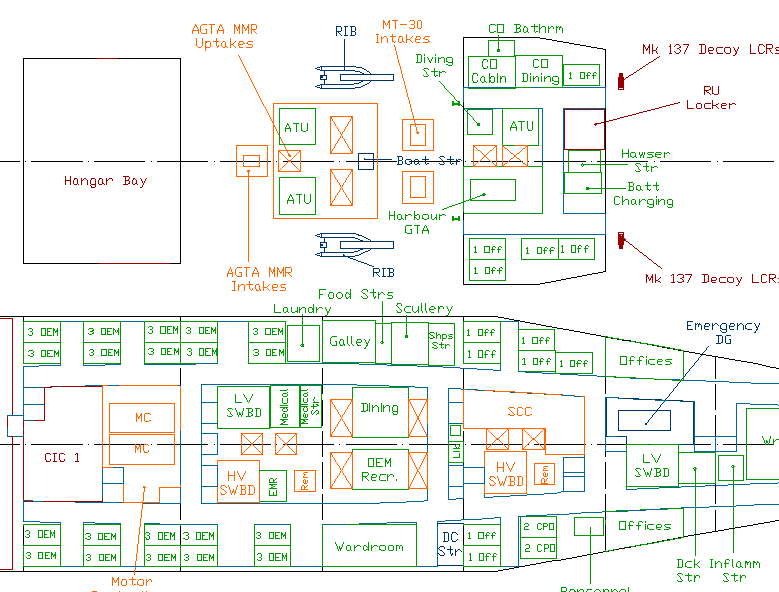
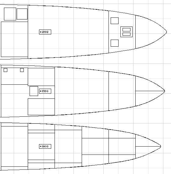
Figures 7, 8 and 9 compare sections of the general arrangements for these vessels. The Type 22 Batch III model was complicated not just by the addition of the connectivity items, but by the modelling of a complete in service ship design, rather than the much simpler early stage model. This complication greatly increased the time to develop the baseline and variant models, and reduced the flexibility for change based on the results of the simulations. Two reduced levels of detail were thus investigated; an intermediate level of detail, with many of the smaller spaces removed, and features such as groups of cabins represented as single spaces; and a low level of detail retaining only the watertight subdivision and access routes.
As outlined in the report, an important demonstration was that the HPM technique was applicable to both the high and low level of details, so showing that it can be applied to early stage ship design. |
|||||||||||||||||||||||||||||||||||||||||||
Return to top |
Project Publications 1. Andrews, D J, “The Use of Simulation in Preliminary Ship Design, Proceedings of 12th International Conference on Computer Applications in Shipbuilding”, Busan, Korea, August 2005, pp 419-432. 2. Andrews, D J, Pawling, R and Casarosa, L, “Integrating Ergonomics into Ship Design”, CETENA Human Factors Conference, Genoa, October 2005, Proceedings on CD; copy held by UCL. 3. Andrews, D J, Pawling, R, Casarosa, L, Galea, E R, Deere, S, Lawrence, P, Gwynne, S and Boxall, P, “Integrating Ship Design and Personnel Simulation”, INEC, IMarEST WMTC, London, 6 - 10 March 2006, Proceedings on CD, ISBN 1-902536-54-1. 4. Andrews, D J, Casarosa, L and Pawling, R, "Integrating the Simulation of Operations Into Preliminary Ship Design", NAV 2006; International Conference on Ship and Shipping Research, Genoa, 21 - 23 June 2006, Vol. 1, pp 4.3.1-4.3.12. 5. Andrews, D J, “Simulation and the Design Building Block approach in the design of ships and other complex systems”, 2006 Proc. R. Soc. Vol. 462, pp 3407-3433. 6. Andrews, D J, Pawling, R, Casarosa, L, Galea, E R, Deere, S and Lawrence, P, “Integrating Personnel Movement Simulation into Preliminary Ship Design”, RINA Int. Conf. on Human Factors in Ship Design, London, 21-22 March 2007, pp 117-128. 7. Andrews, D J, Pawling, R, Casarosa, L, Galea, E R, Deere, S and Lawrence, P, “Integrating Personnel Movement Simulation into Preliminary Ship Design”, RINA IJME, to be published Vol. 150 Part A1 2008. 8. Galea, E R, “The next step in the rise of maritime human factors simulation models : Optimising vessel layout using human factors simulation”, Key Note Address, The Rise of Maritime Simulation, Ocean Innovation 2007, Halifax, Canada, 21-24 Oct 2007. 9. Deere, S J, Galea, E R and Lawrence, P, “A Systematic Methodology to Assess the Impact of Human Factors in Ship Design”, Applied Mathematical Modelling, to be published Vol 32, 2008. 10. Deere, S J, Galea, E R and Lawrence, P, “Optimising Vessel Layout using human factors simulation”, Pedestrian and Evacuation Dynamics 2008, 27-29 Feb 2008 Wuppertal, Germany, To appear 2008. 11. Deere, S J, Galea, E R and Lawrence, P, “Assessing Naval Ship Design for Human Factors Issues Associated with Evacuation and Normal Operations”, COMPIT08, 21-23 April 2008 Liege Belgium, To appear 2008. 12. Andrews, D J, Casarosa, L and Pawling, R, "Interactive Computer Graphics and Simulation in Preliminary Ship Design", COMPIT08, 21-23 April 2008 Liege Belgium, To appear 2008. |
>> Paper Link << |
||||||||||||||||||||||||||||||||||||||||||
Return to top |
Further Information For further information, please contact: Prof. David Andrews Professor of Engineering Design UCL Department of Mechanical Engineering tel: 020 7679 3874 fax: 020 7388 0180 Dr. Rachel Pawling Lecturer in Ship Design UCL Department of Mechanical Engineering tel: 020 7679 5711 Dr. Lorenzo Casarosa Research Student UCL Department of Mechanical Engineering tel: 020 7679 5711 |
>> Profile Link << |
||||||||||||||||||||||||||||||||||||||||||
Copyright © 2008 UCL
|
||||||||||||||||||||||||||||||||||||||||||||